LibreCAD v2.2.0 - User Manual
This is an interim release of the of the LibreCAD User Manual and is subject to change.
The manual is based on LibreCAD v2.2.0-rc1 with a few additions. If you are using another version of LibreCAD, your mileage may vary.
Dock Widgets
Dock widgets are small movable windows that serve two purposes: (1) quick access to the drawing tools, and (2) access to additional features not available from a menu including:
- Block List,
- Command Line,
- Layer List,
- Library Browser, and
- Pen Wizard.
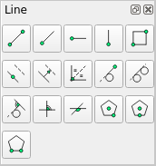
Drawing tool dock example: Line
As an alternative to the Tools menu, the Dock widgets provide more convenient way to access the Drawing Tools:
- Circle,
- Curve,
- Dimension,
- Ellipse,
- Info,
- Line,
- Modify, and
- Polyline.

Dock Widget Areas
Dock widgets can be moved to different areas by “grabbing” (left clicking and dragging) the title bar of the widget and releasing it in a new location. A widget can be left floating inside or outside of the drawing window, or placed in one of the four dock areas (left, right, top or bottom). The Dock Areas toolbar allows widgets to be hidden or made visible depending on their location:
| Tool | Icon | Description |
|---|---|---|
| Left | Shows / hide the dock widgets located on the left side of the drawing window. | |
| Right | Shows / hide the dock widgets located on the right side of the drawing window. | |
| Top | Shows / hide the dock widgets located on the top of the drawing window. | |
| Bottom | Shows / hide the dock widgets located on the bottom of the drawing window. | |
| Floating | Shows / hide the dock widgets floating within the drawing window or outside of the drawing window. |
Widgets can be placed either on top of an existing widget in any of the dock areas creating a tab for each of the widgets. Widgets can also be place above or below an existing widget dividing the area into multiple sections.
In addition, dock widgets can be resized by clicking and dragging the edge of the widget’s box. A widget has a minimum width of five icons and can be no shorter than the default height.
Block List Dock
The Block List Dock provides the functions to manage blocks and a list of blocks that are active in the drawing. Block functions include:
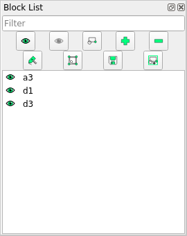
Block List dock example - 3 blocks
| Icon | Description |
|---|---|
| ”Show all blocks” - Makes all the blocks in the current drawing visible. | |
| ”Hide all blocks” - Hides all blocks in the active drawing. | |
| ”Create a block” - Creates a block from the selected items. | |
| ”Add an empty block” - Creates an empty block that can then be edited is a separate window (see below). | |
| ”Remove the active block” - Deletes the highlighted block. | |
| ”Rename the active block” - Rename the highlighted block. | |
| ”Edit the active block in a separate window” - Open a new drawing window to edit a new or existing block. | |
| ”Save the active block to a file” - Saves the highlighted block to a file. | |
| ”Insert the active block”. - Inserts the highlighted block in the current drawing at the specified reference point |
The lower portion of the dock shows a list of blocks in the current drawing. The blocks in the above example are named “a3”, “d1”, and “d3”. More details on creating and using blocks can be found in the User Guides.
Command Line Dock
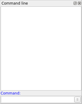
Command Line dock
The Command Line is for users that want to draw by using keyboard commands. Commands, such as “li” for a line, “cir” for a circle, etc, are entered at the command line along with the required parameters (e.g. start and end coordinates for a line). Using the command line can be faster and/or more precise than drawing using exclusively a mouse and toolbars. The available commands are listed with the Drawing Tools and Snapping tools. There are also commands available for Edit and View operations.
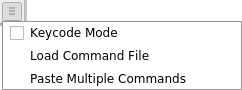
Command Line dock drop-down menu
The dock includes a drop-down menu that offers additional functions:
- Toggle Keycode Mode off or on.
- Load a Command file.
- Paste commands.
Further details on using the command line are in the User Guides. In addition to command input, the command line provides access to a built in calculator. The calculator can be invoked with the cal command. The available operators and functions can be found in the Appendix.
Note
LibreCAD is designed with emphasis on mouse input and at the moment some options can be only selected by using the mouse as there is no equivalent command.
Layer List Dock
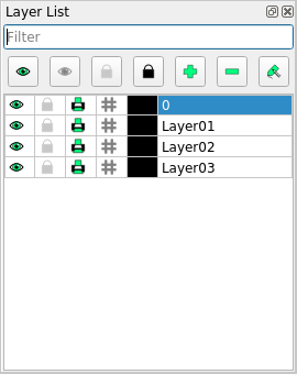
Layer List dock example with 4 layers
The Layer List Dock provides a list of layers in the current drawing and the functions required to manage them. There are three sections in the dock:
- the list filter,
- the list operators and functions, and
- the layer operators and functions.
The list filter is the input box at the top of the dock. It provides the ability to filter a long list of layer names to help locate a layer. Enter a text string, the name or partial name of a layer, in the input box to filter the layer or layers. Wildcards (“*” or “?”) can be used to filter the list to locate similar layer names (e.g. “*01” would show all names ending by “01”).
The icons on the top of the layer list allow operations to the entire list of layers. Those operations include:
| Icon | Function | Description |
|---|---|---|
| Show all layers | Makes all the layers in the current drawing visible. | |
| Hide all layers | Hides all layers in the current drawing. | |
| Unlock all layer | Unlock, or ”Defreeze”, all layers to allow changes to the entities in the layer. (*) | |
| Lock all layer | Lock, or ”Freeze”, all layers to prevent unintentional changes. (*) | |
| Add a layer | Add a new layer to the list. (Shortcut [Ctrl]+[L]) (*) | |
| Remove layer | Remove the highlighted layer from the list. (*) | |
| Modify layer attributes / rename | Modify the selected layer’s attributes and / or rename the layer. (*) |
The lower portion of the dock shows a list of layers in the current drawing and are listed in alpha-numeric order. In the example above the layers are named “Layer01”, “Layer02”, and “Layer03”. Note that layer 0 is a special layer and should not be used for general drawing purposes.
Icons to the left of each layer act on the layers individually. The layer operations are:
| Icon | Description |
|---|---|
| Show / hide the selected layer. (*) | |
| Lock / unlock the selected layer. (”Freeze” / ”Defreeze”) | |
| Print / don’t print the selected layer. (*) | |
| Toggle construction lines. (*) A layer designated as a ”Construction Layer” is special layer used to create reference geometry to help align other drawing entities. Construction lines are intended as temporary guide lines and drawn to ”infinity”. | |
 |
Shows the layer’s assigned color (the default is Black). |
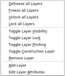
Layer list or individual layer operations can also be accessed by right-clicking on a layer. Right-clicking in the list window opens a popup menu that provides equivalent operations to the item marked with an asterisk (*).
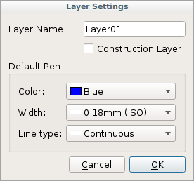
Clicking the Attribute icon ![]() allows users to change the pen attributes of all entities on the selected layer. Entities that have their own pen attribute set differently will override the layer’s attributes.
allows users to change the pen attributes of all entities on the selected layer. Entities that have their own pen attribute set differently will override the layer’s attributes.
The attributes include:
| Attribute | Description |
|---|---|
| Layer Name | The default layer name is “O”, but any alpha-numeric label can be used. New layers are created with the name of the highlighted layer with a sequence number appended. Layers are sorted in the list alpha- numerically. |
| Construction Layer | Toggle the construction lines off / on. |
| Default Pen: |
|
More details on creating and using layers can be found in the “Drawing Setup” section of the User Guides.
Library Browser Dock
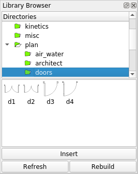
Library Browser dock example
The Library Browser Dock shows blocks available from the defined libraries and allows users to insert blocks into the current drawing. To insert a block, select a block from one of the categories by clicking on it, e.g. “d1” and click the “Insert” button. Specify a reference point in the drawing window with a mouse click or by entering coordinates at the command prompt. Once inserted into the drawing, the block is shown in the Block List Dock.
LibreCAD includes several libraries and additional libraries can be specified by defining a path to user libraries in the Application Preferences, “Path” tab as shown in Getting Started.
Pen Wizard Dock
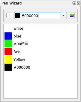
Pen Wizard dock example
The Pen Wizard allows users to create a palette of favorite colors for the drawing tools. Colors can be selected from the existing colors via the drop-down list or created as a custom colors via the  button to the right of the drop-down list. Pressing the “Add to favorites” [
  ] button to the left will add the color to the list of favorites below. Drag-and-drop the colors in the list to arrange them in the preferred order.
Once colors have been added to the list, set the active pen color by double-clicking a favorite color.
Right-clicking a favorite color allows users to:
- Select all objects of a specific color and clicking on “Select objects”
- Change the color of all selected objects by clicking on “Apply to selected”
- Delete a favorite color by clicking “Remove”